As-built reconstruction · Installed January 2016 · Revision D

2009 Buell Ulysses Top Case Integrated Lighting

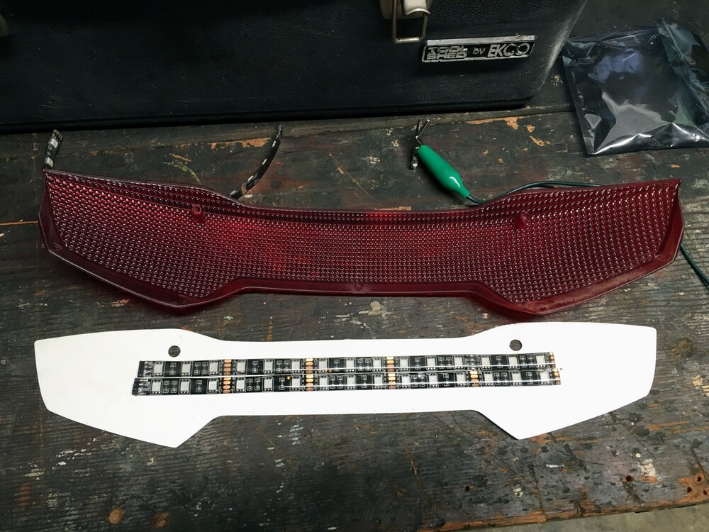
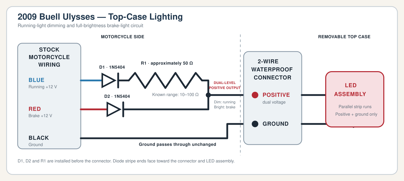
A single LED assembly serves as both running light and brake light. The running-light branch is current-limited for reduced brightness; the brake branch supplies full voltage.

Functional schematic

Blue: running +12 V Red: brake +12 V Black: ground
Wiring schematic showing the two 1N5404 diodes and dimming resistor before the two-wire waterproof connector, with combined positive and ground continuing to the top-case LED assembly.

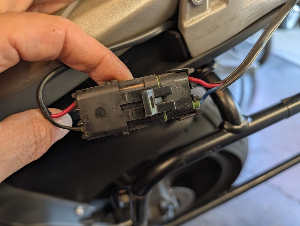
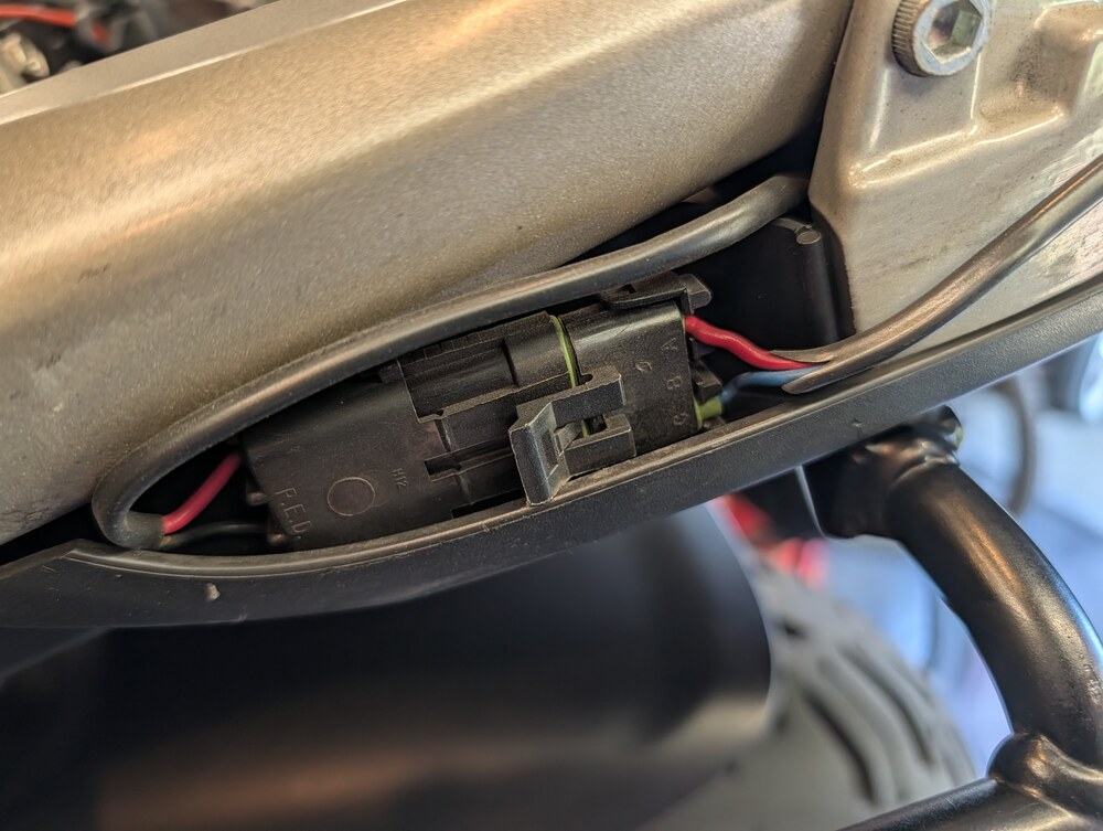
Connector / harness

LocationWireFunction
Motorcycle loomBlueRunning-light +12 V input
Motorcycle loomRedBrake-light +12 V input
Motorcycle loomBlackGround
2-wire connectorPositiveCombined dim/bright output
2-wire connectorGroundGround return to LED

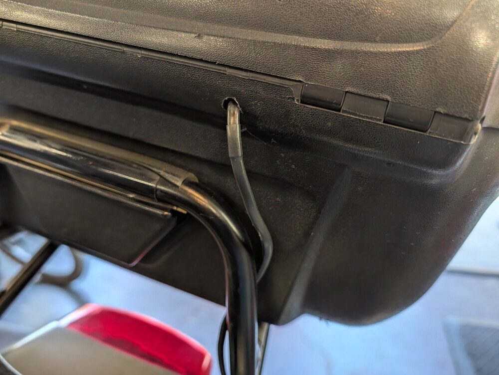
The resistor and both diodes are in the motorcycle-side loom before the removable waterproof connector. Only positive and ground continue into the top case.

Operating logic

ConditionCurrent pathResult
Running onlyD1 and R1Dim
Brake appliedD2 bypasses R1Bright
Both activeBrake branch dominatesBright
Key off / no brakeNo positive feedOff

D1 and D2 are 1N5404 isolation diodes. R1 is believed to be 50 Ω and is known to fall between 10 and 100 Ω. Measure R1 if the loom is opened.

Installation photographs